Battery discharged.
The method of discharging the battery has a decisive influence on the durability of the battery, mainly the value of the current drawn and the discharge time.
Wyładowaniu akumulatora …
Okęcie airport parking – Warsaw
Chopin airport parking

The method of discharging the battery has a decisive influence on the durability of the battery, mainly the value of the current drawn and the discharge time.
Wyładowaniu akumulatora …
1. Top up:
• it is charging, the purpose of which is to replenish the electric charge in the battery,
• stosować tu …
Ways to charge the battery.
Charging methods:
1. At a constant voltage value:
• na końcówkach akumulatora utrzymuje się stałą wartość napięcia podczas …
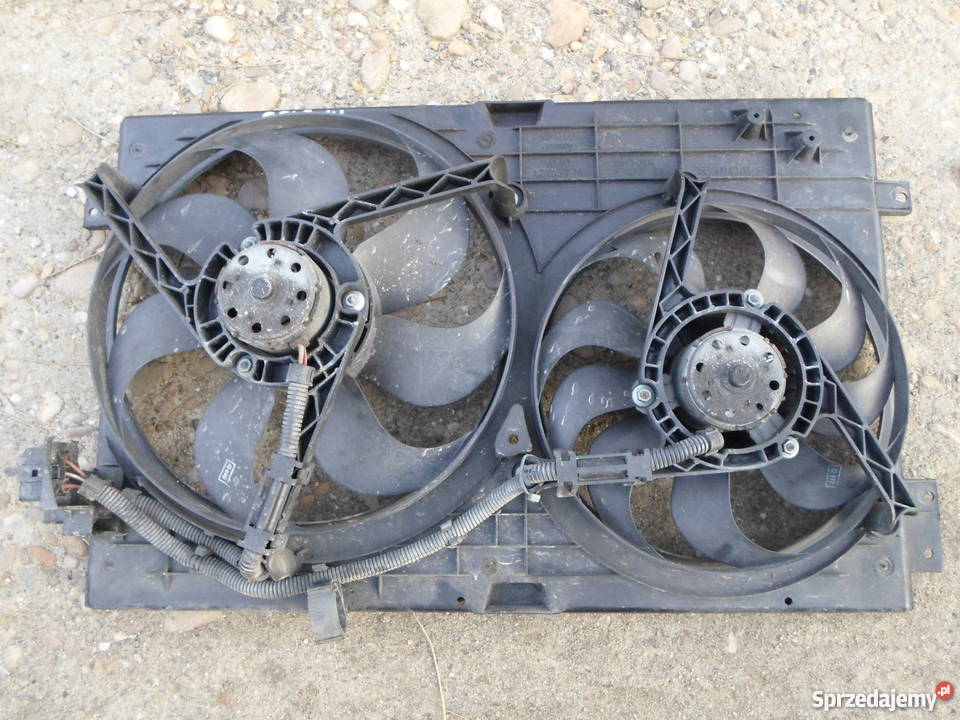 Fan failure
The radiator fan turns on only at high engine loads. W razie jego uszkodzenia nie musisz rezygnować z dalszej …